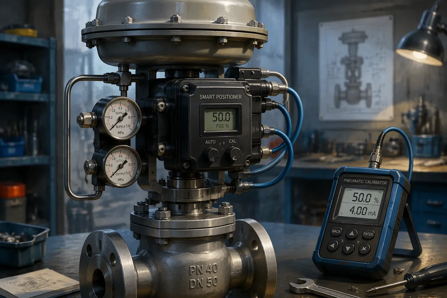
A control valve positioner is a device that checks the valve stem position and adjusts the actuator air pressure to match the control signal. This device makes sure the valve reaches the exact position the controller asks for. Engineers often ask: what positioner types exist, and how does one pick the best option for a specific application? A positioner helps a valve achieve accuracies within 2% of set point. It also overcomes stem packing friction and minimizes deadband. This article explains positioner types, selection criteria, installation, calibration, and maintenance practices.
Key Takeaways
- A control valve positioner makes sure the valve stem moves to the exact spot the controller wants.
- Positioners get past stem friction and lower deadband so control is more accurate.
- Use a positioner when you need high accuracy, a fast response, or a high-pressure drop.
- Pneumatic positioners work without electricity in dangerous areas.
- Electro-pneumatic positioners change electrical signals into air pressure.
- Digital positioners can self-calibrate, run diagnostics, and use communication protocols like HART.
- Installing them the right way and taking care of them often keeps positioners working well.
- Choosing the right positioner improves control, cuts downtime, and extends valve life.
What Is a Control Valve Positioner
Definition and Function
A control valve positioner is a closed-loop device that makes sure a valve stem reaches the exact spot a controller wants. It gets a control signal, compares it to the real stem position, and changes actuator air pressure until the error is zero. This device works like the brain of the valve assembly. It sends a corrective signal to remove process offset. The positioner sits between the controller, like a DCS or PLC, and the actuator. The controller sends a signal to the positioner. Then the positioner moves the actuator to adjust the valve. It also checks the process condition and compares it to the set point. This setup creates a closed-loop system that keeps the valve in the right place.
Positioner vs. Actuator
A valve positioner and an actuator do different jobs in a control loop. The actuator is the power source. It turns pressure into mechanical motion using diaphragms, springs, or cylinders. This motion pushes the valve stem or shaft toward the needed position. The positioner works as a middle controller. It gets a 4–20 mA signal from the controller, turns it into pneumatic output, and sends it to the actuator. The actuator is the final part that actually moves the valve. The positioner uses a feedback element to close the loop with the actuator stem position. In short, the actuator does the action, while the positioner makes sure it is accurate.
Key Components
A typical control valve positioner has several main parts inside. A position sensor finds the real valve position and sends this data back to the control unit. A pneumatic amplifier raises or lowers air pressure to the actuator. A feedback linkage or cam links the valve stem to the positioner mechanism. A nozzle and flapper assembly, or an I/P converter in electro-pneumatic models, turns electrical signals into pneumatic pressure. These parts work together to fix any gap between the commanded position and the real position. Engineers and technicians should know these parts to install, calibrate, and troubleshoot valve positioners well.
Why Use a Positioner
Overcoming Friction
Stem packing friction causes a hard problem in valve control. The packing holds the stem tight to stop leaks. This hold resists movement and makes the valve stick. A valve positioner solves this by sending more air pressure to push past the friction. The positioner sees the stem has not moved and raises output until it moves. This action breaks the static friction and lets the valve travel smooth. Without a positioner, the actuator must handle this friction by itself. The result is a valve deadband that can be several percent of travel. A positioner lowers this deadband to a much smaller value. The valve then responds to small signal changes that the actuator alone would miss.
A positioner also fixes packing wear over time. As the packing gets older, friction changes. The positioner changes its output to match the new conditions. This self-fixing action keeps the valve accurate during its whole life. Plants that use positioners report fewer issues with sticky valves and better control. The table below shows benefits from plants that added positioners to their valves.
| Company / Plant | Reported benefit of using a positioner on a control valve |
|---|---|
| Usina Coruripe Plant, Campo Florido Unit | Stabilized plant operation; reduced repair costs; lessened worker burden |
| NS Styrene Monomer Co., Ltd., Oita Works | Improved monitoring of valve status; high plant operation stability |
| Showa Denko K.K., Kawasaki Plant | Optimized maintenance work; reduced maintenance costs |
| Eastern Petrochemical Company (SHARQ) | Improved maintainability; greatly reduced maintenance workload; enabled predictive maintenance |
| Daikin Industries, Ltd., Kashima Plant | Significantly reduced maintenance costs; established quick handling of minor malfunctions and warning signs |
| Mitsubishi Chemical Corporation, Ibaraki Plant | Improved maintenance by identifying valve problems and warning signs |
Improving Response Time
A positioner speeds up response time by making the air path to the actuator shorter. The positioner sits near the actuator and gives air directly. This short path lowers the amount of air that must move for each stroke. The valve gets to its target position faster. This speed is important in fast processes where the controller updates often. A slow valve causes lag in the control loop. The loop then shakes or cannot hold the set point. A positioner with high gain fixes errors fast and keeps the loop stable.
The feedback loop inside the positioner also makes accuracy better. The device always checks the command signal against the real stem position. Any difference between them starts a quick fix. This always-on feedback keeps the valve on target even when supply pressure or process load changes. The result is tighter control and less change in the process variable.
Split-Ranging and Characterization
Split-range control lets one controller signal run two valves. Each valve responds to a different part of the signal range. A positioner makes this work by changing its zero and span. Common applications include:
- Chemical reactor temperature control: A dual-output controller runs a fail-closed hot water valve and a fail-open cold water valve. Each positioner is set to half range.
- pH control: A floating valve position controller handles acid and base addition through two valves. This gives sensitivity and fast response.
- General split-range pneumatic systems: Adding a positioner to at least one valve makes response time better by needing less air volume.
Valve characterization is another big benefit. The positioner can shape the valve’s flow curve to match process needs. It changes the link between signal and stem position. This shaping fixes non-linear valve trim or process gain. Engineers use characterization to make the loop linear and improve control quality. Valve positioners thus give flexibility that a plain actuator cannot match.
When a Positioner Is Needed
Required Applications
Some process conditions need a valve positioner. Without one, the valve stem position depends on the balance between actuator air pressure and spring force. Stem packing friction throws off this balance a lot. A valve with 2 bar of equal frictional force needs a 2 bar change in actuator pressure to break free. In a 3–15 psi (0.2–1.0 bar) actuator range, this friction causes a 200% deadband. The valve would not react to small signal changes. Well-kept valves usually have 2–8% deadband. Worn valves with packing that is too tight may hit 15–25%. Without a positioner, this deadband directly limits how precise process control can be.
Eight specific conditions call for a positioner:
- High positioning accuracy: A positioner removes hysteresis and friction so the stem reaches the exact position asked for.
- Faster valve response: It gives higher air pressure and volume so the valve reacts faster to signal changes.
- High opening or closing forces: It works as a pneumatic amplifier against high differential pressures.
- High pressure drop: Needed when the drop is more than 5 bar for single-seated valves or 10 bar for double-seated valves.
- Non-linear actuator characteristics: It makes valve travel more linear for better controllability.
- Fluctuating process conditions: It adjusts on its own as differential pressure changes to keep the plug in the right spot.
- Wide throttling range: It boosts accuracy across the full stroke during fine modulation.
- Viscous or slurry fluids: It gives extra power to get past stem sticking or drag.
Split-range control is one specific use where valve positioners are a must. One controller output runs two or more valves. Each valve reacts to a different part of the signal range. For example, 0–50% drives a small valve for fine control. 51–100% drives a larger valve for high flow. This means you must calibrate each valve positioner to respond to its assigned signal range.
Recommended Applications
A modulating valve that must hold an exact position under tough conditions gains from a positioner. High-friction valves need a positioner to get past packing drag. High-pressure-drop valves need one to work against unbalanced forces. Large valves with long strokes need the extra air volume a positioner gives. Split-range loops need positioners to assign different signal ranges to each valve. Fast-response loops need a positioner to cut lag and stop oscillation.
The rule of thumb for engineers says: use a positioner when the valve sees high seat friction, a large pressure drop, a long stroke, or a control loop that must settle fast and stay accurate. A plain actuator falls short of the set point in these cases. A positioner also helps when process conditions change during operation. The device adjusts on its own to keep the right position. This self-correction keeps the loop steady without an operator stepping in.
Unnecessary Applications
Not every valve needs a positioner. On-off valves do not need one. The valve opens all the way or closes all the way. The actuator alone does this job. Slow processes with wide control bands may not gain from a positioner either. The added precision gives no real benefit. Applications with steady process conditions and low friction run fine without one. A bypass line that only opens or closes now and then does not need a positioner. The cost of the device is more than any benefit. Engineers should look at each application on its own. The choice depends on process needs, not on general rules.
Types of Control Valve Positioners
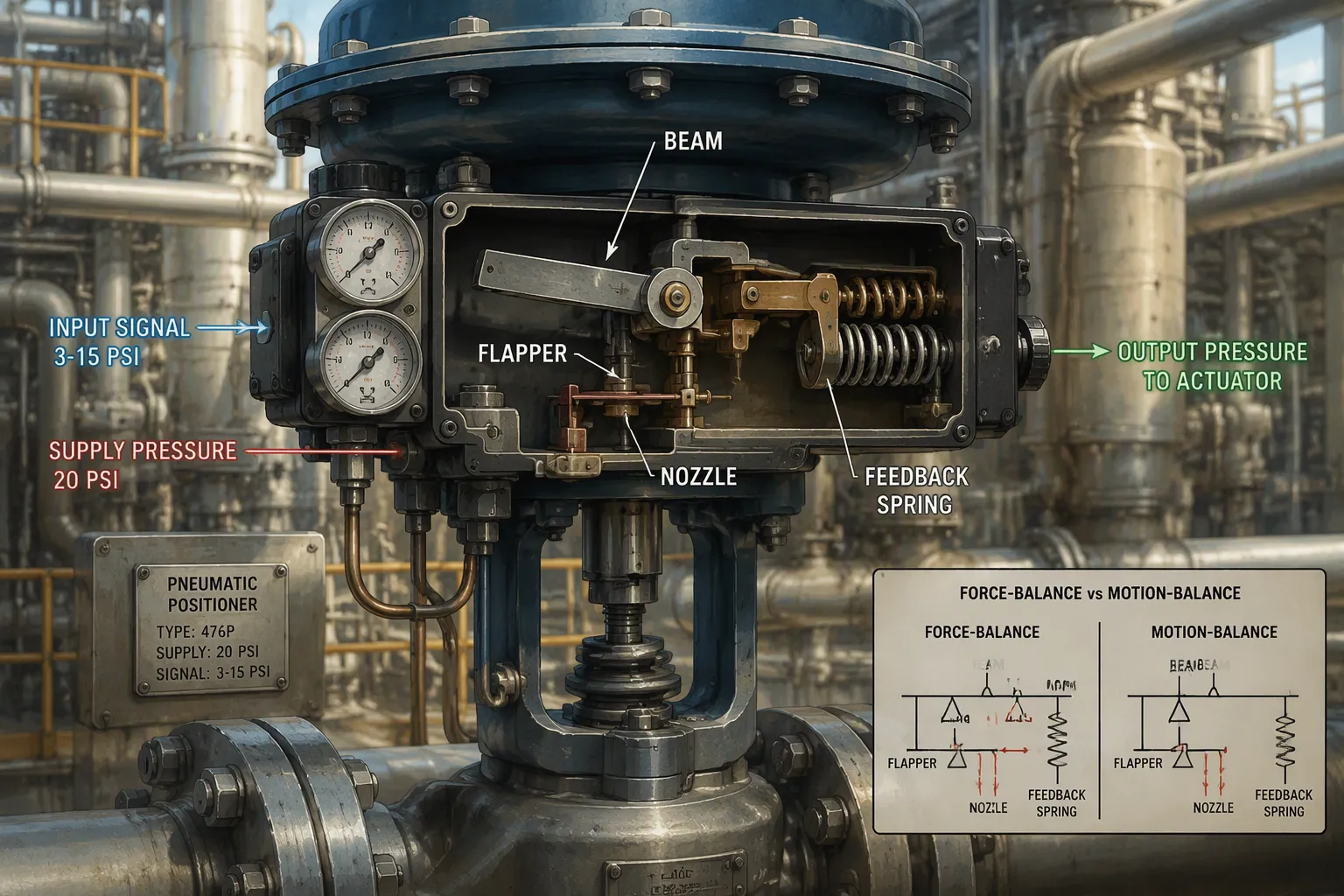
There are three main types of control valve positioners used in industry today. Each type works for different process needs and places. Engineers need to know these designs to pick the right device. The three types are pneumatic, electro-pneumatic, and digital. Knowing these valve positioners helps you match the device to the job.
Pneumatic Control Valve Positioner
A pneumatic control valve positioner gets a pneumatic signal. This signal is air or gas pressure in a pipe. The positioner compares this signal to the real valve stem position. Then it changes the actuator pressure to move the valve. A pneumatic positioner does not need electric power. This makes it great for very hot, cold, or explosive places. Electronic devices could break or cause a spark in those places.
Force-Balance Design
The force-balance design uses a beam and flapper setup. A pneumatic signal comes in and pushes on one side of a beam. The valve stem position pushes on the other side through a feedback spring. When these forces match, the valve stays in place. If the control signal shifts, the beam tips. This changes the nozzle back-pressure. The pilot valve then adjusts actuator pressure until the forces match again.
Motion-Balance Design
The motion-balance design uses a different setup. The input signal moves a flapper closer to or farther from a nozzle. The valve stem position feeds back through a cam and linkage. This feedback moves the nozzle assembly the other way. The gap between flapper and nozzle sets the output pressure. Motion-balance designs let you change control characteristics in the field. One multi-lobe cam gives linear, split-range linear, and equal percentage curves. You can get custom curves with a special order.
The Masoneilan 4700P/4800P models are a common pneumatic control valve positioner. These models use parts inside that resist rust. The pilot valve is the only moving part in the pilot housing. Technicians can take it out without taking apart other parts. A bypass valve module lets you do maintenance while running the valve directly.
Electro-Pneumatic Positioner
Electro-pneumatic positioners link electronic control systems to pneumatic actuators. These devices are also called I/P positioners. The word electropneumatic describes this conversion tech. They take an electric signal and turn it into pneumatic pressure.
I/P Conversion
The I/P converter turns a 4-20 mA DC current signal into a corresponding pneumatic pressure. The pressure is adjusted according to the signal to position the valve. Mechanical feedback from the valve stem fine-tunes the actuator pressure.
Analog Signal Operation
An electro-pneumatic positioner takes a 4-20 mA current loop. The control sequence follows a closed loop. The positioner gets the control signal from the system. A sensor measures the real valve position all the time. The desired position is compared to the real position. The difference is the error signal. Based on this error, the positioner changes the air pressure to the actuator and moves the valve. The whole process repeats over and over.
The Masoneilan 4700E/4800E models give fast response and exact positioning for process jobs. These electro-pneumatic positioners make valve positioning better.
Digital Positioner
Digital positioners use microprocessor-based control. These devices are often called smart positioners. They offer features beyond analog or mechanical units.
Microprocessor Control
A microprocessor-based positioner gets the input signal digitally. The internal processor compares the setpoint to the real stem position. It figures out the needed output with high precision. Digital positioners have fewer moving parts than analog types. The device can do automatic self-calibration. This cuts down on human error during setup. Maintenance crews can set up the unit with push buttons, a handheld communicator, or a laptop.
Communication Protocols
Smart positioners support digital communication protocols. This lets two-way communication happen without extra wiring. A technician using digital communication can read valve diagnostics or change settings from afar. Digital protocols carry the control signal and diagnostic data on the same wire.
A digital positioner gives advantages over analog positioners. It can provide diagnostics such as monitoring travel, air consumption, and friction. Real-time data enables predictive maintenance. Setup is done electronically via push buttons or a laptop.
Each type of control valve positioner has a special purpose. Pneumatic units work in hazardous areas without electricity. Electro-pneumatic units link electronic controllers to pneumatic valves. Digital units offer diagnostics and remote communication. Engineers should match the positioner type to the application conditions and available infrastructure.
Analog vs. Digital Positioners
Performance and Accuracy
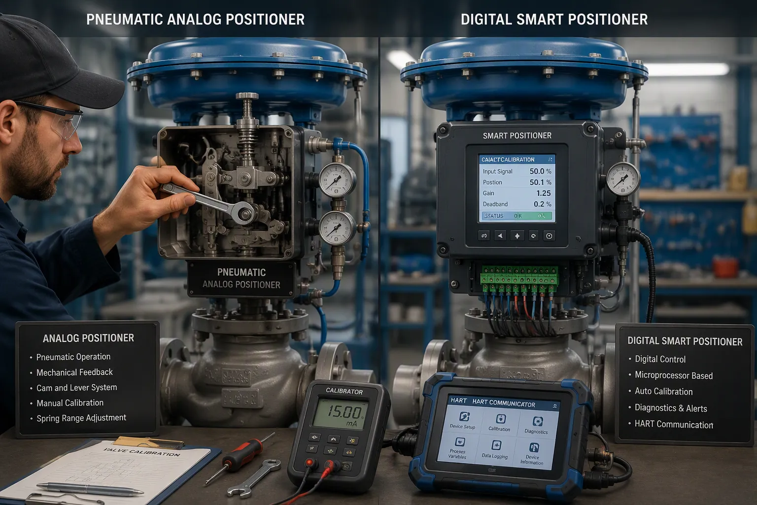
The difference between analog and digital positioners is about how well each holds the valve stem. Analog positioners, including pneumatic and electro-pneumatic types, have higher deadband than digital positioners. Digital positioners have lower deadband and better repeatability. A digital positioner self-calibrates and auto-tunes. This action keeps deadband low with no calibration drift. Analog positioners need manual calibration from time to time. Their deadband and hysteresis can get worse between service visits. A drifting positioner makes the control loop work harder. The loop then struggles to hold the set point.
Setup and Diagnostics
Setup is very different for these two types. On an analog positioner, a worker must adjust cams and linkages by hand. The task takes time and depends on skill. A digital positioner self-calibrates. It adapts to the valve assembly on its own. Commissioning becomes fast and repeatable with little human error.
Diagnostics are the biggest gap. Analog positioners have no internal diagnostics. They cannot monitor air pressure, shaft position, or housing temperature. They cannot detect a jammed valve or low air supply. Digital positioners keep an eye on all these things and can set off software alarms.
| Feature | Digital Positioners | Analog Positioners |
|---|---|---|
| Digital communication | Two-way digital communication lets the positioner send and receive digital data | One-way analog signal only (3–15 psi pneumatic or 4–20 mA electrical); no digital communication |
| Internal diagnostics | Can check internal parts (air pressure, shaft position, housing temperature) and valve behavior; supports predictive maintenance and software alarms | No diagnostic skills; cannot monitor internal parts or valve behavior |
| Self-calibration / auto-tune | Microprocessor-based self-calibration (auto-tune/auto-adjust) gives fast, repeatable setup without human help | No self-calibration; manual calibration needed |
| Remote monitoring and feedback | Digital data stream gives valve position feedback without extra analog input; data can be stored inside and read with a handheld or laptop | Needs extra analog input (4–20 mA position signal) for feedback; no internal storage or remote readout |
| Alarm and fault detection | Can make software alarms for abnormal conditions (e.g., valve stuck, low air pressure, physical damage) | No alarm or fault detection |
Smart digital positioners provide auto-tuning, valve position feedback, online diagnostics, fault alarms, predictive maintenance, and asset management. The industry is moving from simple positioning control toward full valve health management. These features improve valve accuracy, reduce compressed air use, cut unexpected shutdowns, improve plant safety, and extend valve life. A front display with buttons lets users set up and find faults right on the device.
Cost and Lifecycle
Analog positioners cost less to buy. Their simple mechanical design works well in hazardous areas where electric power is not available. A pneumatic unit needs no electricity and runs in extreme temperatures. These benefits keep analog positioners useful in many plants.
Digital positioners cost more at first. But their value over the life of the device often makes up for it. Built-in diagnostics allow real-time monitoring and fault detection. Predictive maintenance cuts downtime by predicting valve failures. Better valve health comes from always collecting and analyzing data. These features reduce unexpected shutdowns and extend valve life. A plant avoids lost production and unsafe events when it finds a failing valve early. Analog positioners cannot give this early warning. Maintenance crews find problems only during routine checks or after a failure.
The choice depends on the application. A simple on-off or low-precision loop may work fine with an analog unit. A critical modulating loop that needs high uptime gains from digital diagnostics. Engineers should weigh purchase cost against the cost of downtime, manual calibration labor, and compressed air use. Both designs have a place in modern plants.
Selecting a Positioner
Eight Selection Guidelines
Picking the right valve positioner means looking at many things. Industry experts suggest eight key guidelines to match the device to the job.
- Actuator motion and feedback matching — Linear globe valves need stem-travel feedback. Rotary ball and butterfly valves need shaft-rotation feedback. Bad brackets or linkage geometry can cause position error even with a correct 4-20 mA signal and normal air supply.
- Fail action confirmation — Engineers must confirm fail-open, fail-closed, or fail-last behavior before ordering. Reversed positioner action can drive the valve the wrong way during commissioning.
- Instrument air quality — Wet, oily, or unstable air makes the positioner stick or drift. Air quality sets real limits on performance.
- Air supply pressure — The regulator must give enough pressure for the actuator but stay within positioner and actuator limits. Pressure drops during compressor cycling can cause slow movement, incomplete stroke, or a mismatch between command and feedback.
- Actuator volume and booster need — Large actuators may need more output capacity than the positioner relay can give. A volume booster may be needed when stroke speed matters.
- Control signal and communication — A basic analog loop may only need 4-20 mA. A DCS loop may require digital communication, local display, or diagnostic alerts. Split-range control applications need extra calibration to assign each valve to a distinct part of the signal range.
- Hazardous-area requirements — Hazardous-area service changes the enclosure and approval requirements for the positioner.
- Integration with the complete valve package — For a new control valve package, check these details with the valve and actuator together. Do this instead of adding them after the valve body has been selected.
Matching to Actuator and Valve
Positioners bridge the gap between control systems and actuators. Most actuators run at air pressures well above the 3-15 psig output of traditional pneumatic control systems. A positioner amplifies the signal, so higher-pressure actuators work with lower-pressure control signals. It also connects pneumatically operated actuators to control systems using 4-20 mA or digital signals. Picking the correct valve positioner prevents compatibility issues during commissioning.
Engineers must identify the actuator foundation first. Pneumatic versus electric, quarter-turn versus linear, and double-acting versus spring-return each determine mounting points, travel characteristics, and compatible feedback devices. For quarter-turn assemblies, verify the actuator output drive size and shape. Confirm mounting dimensions match the appropriate standard pattern. For linear actuators, check the stem connection type and yoke dimensions. The bracket and coupler need careful confirmation. Do not assume a visually similar assembly will fit.
Environment and Safety
Environmental conditions directly affect selection of valve positioners. Hazardous area classifications determine the required enclosure protection and approval certifications. These standards make sure the positioner cannot ignite flammable gases or dusts.
Safety instrumented systems impose additional requirements. For service in safety loops, engineers must specify positioners with appropriate safety certification. These devices undergo rigorous testing to show predictable failure behavior. Many digital positioners also support partial-stroke testing, which allows verification of safety valve operation without a full shutdown.
Temperature range and vibration levels also matter. Positioners installed outdoors in cold climates need appropriate temperature ratings. High vibration can cause mechanical wear or calibration drift over time. Engineers should verify the positioner meets the site conditions before installation.
Installation Best Practices
Mounting and Linkage
A good mount keeps the valve positioner lined up with the actuator stem for the whole stroke. The bracket must sit flat and square on the actuator yoke. Bolts should be tightened evenly so the linkage does not twist. A twisted bracket makes the feedback arm stick. Then the valve hunts or jams at some positions. Technicians should compare the linkage shape to the maker’s drawing before they tighten anything. A bad mount shows up as a dead band at the ends of the stroke. Good alignment fixes this problem.
The linkage arm joins the positioner spindle to the valve stem or shaft. For linear valves, the arm must stay straight up at mid-stroke. For rotary valves, the coupler must follow the shaft turn without slipping. A loose set screw lets the arm drift. Then the positioner reads a false stem position. A quick wiggle test on the arm shows any play. Any play means the reading is wrong. Technicians should also check the arm length. A wrong arm length changes the travel ratio.
Air Supply and Tubing
Clean, dry instrument air keeps the valve positioner working well. Moisture causes rust inside the relay and nozzle. Oil blocks small passages. The air supply line should have a filter regulator with a drain. Technicians should set the regulator to the pressure shown on the positioner nameplate. Too little pressure makes the stroke slow. Too much pressure can harm the relay. A gauge on the regulator lets the technician check the setting at a glance.
Tubing runs should stay short and direct. Long, coiled lines trap air and slow the response. Sharp bends pinch the tube and block flow. Metal tubing needs proper supports to stop vibration damage. Plastic tubing works for short runs but can crack near heat sources. Every fitting must be leak-tight. A soap bubble test on each joint finds leaks fast. Technicians should also check the tubing diameter. A tube that is too small starves the actuator during fast strokes.
Wiring and Signals
Electrical wiring carries the control signal to the positioner. Technicians should use shielded twisted-pair cable for analog 4-20 mA loops. The shield connects at one end only. This step stops ground loops that twist the signal. Wires must stay away from high-voltage cables. Separation avoids electrical noise on the signal line. Cable trays should route signal wires away from motor feeds and variable frequency drives.
Terminal connections need the right polarity. Reversed wires stop the positioner from responding. After wiring, the technician should check the signal with a multimeter. The reading at the terminals must match the controller output. For digital communication units, the network settings must match the host system. A wrong address blocks communication. A final loop check confirms the valve moves to the commanded position. The technician should command 0%, 50%, and 100% and watch the stem travel.
Calibration and Maintenance
Calibration Procedure
A good calibration begins by shutting off the valve from the process. The technician then hooks up a signal generator to the positioner input. Next, they send test signals across the range and note the real valve position at each step. The zero and span must stay within the specified tolerance. The technician also measures hysteresis and deadband at each point. A digital positioner with digital communication support can run this check on its own and save the results.
After the initial check, the technician adjusts the zero and span using the appropriate screws or digital interface. They run the test again until the error stays inside the tolerance band. For a full yearly calibration, a test with multiple points across the stroke is performed, both upscale and downscale. A deviation curve is drawn, and the I/P transducer output is checked against the input signal.
Maintenance Checklist
Routine maintenance keeps a valve positioner working well. The schedule depends on how critical the application is and the environment. Typical tasks include a full stroke test, travel time measurement, and a review of digital diagnostics. Periodic service adds seat leakage tests and packing inspections. A yearly overhaul covers actuator disassembly, diaphragm and seal replacement, and a full calibration with as-found and as-left readings recorded in the maintenance system.
For preventive maintenance, technicians should calibrate at regular intervals recommended by the manufacturer. Harsh environments may need more frequent checks. They should also calibrate after new installations or actuator replacements. A microprocessor-based diagnostic tool can test the valve in place and find deadband or stiction without a shutdown.
Troubleshooting Common Issues
Oscillation, slow response, and signal failure are the most common positioner problems. When a loop oscillates, the technician first puts the controller in manual mode. If the oscillation keeps going, the cause is likely outside or inside the positioner itself. They then go to the valve and watch the stem for movement. A triangular controller output trend with a square process variable trend points to a control valve problem. Stiction is a common cause, and valve maintenance or positioner tuning usually fixes it.
A miscalibrated positioner can respond too hard or too slow, which causes unstable valve movement. Bad feedback from the stem sensor makes the control system overcorrect or undercorrect. Technicians should check the air supply, look at the linkage for play, and confirm the PID settings. They can also test for deadband by making two controller output changes in one direction and a third in the opposite direction. If the process variable does not return to its starting value, deadband exists in the valve. Accurate valve positioning depends on a clean air supply, a tight linkage, and a correctly tuned loop.
Pneumatic, electro-pneumatic, and digital designs each have different jobs. Pneumatic units work in dangerous places where there is no power. Electro-pneumatic models turn 4-20 mA signals into air pressure. Digital units use a microprocessor to add diagnostics and communication. The right valve positioner gives exact, reliable control, faster response, and longer life.
Engineers should use the eight selection tips and regular upkeep steps from this guide. These steps stop costly downtime and unstable loops.
Smart positioners now work with digital communication and can predict problems. This trend leads to valves that check themselves and report their condition. Plants that use these tools will have fewer surprises and steadier operations.
FAQ
What does a control valve positioner do?
A positioner checks the control signal against the real valve stem position. It then changes actuator air pressure until the two line up. This closed-loop action removes error and keeps the valve on target. The device sits between the controller and the actuator.
How does a positioner differ from an actuator?
The actuator gives the force that moves the valve stem. The positioner works as a middle controller. It reads the stem position and fixes the air pressure sent to the actuator. The actuator does the work, while the positioner keeps it accurate.
When should an engineer specify a positioner?
A positioner helps when stem friction is high, pressure drop is large, or the stroke is long. It also fits split-range loops and fast-response control. On-off valves and slow processes with wide control bands rarely need one.
What are the main types of positioners?
Three main types exist: pneumatic, electro-pneumatic, and digital. Pneumatic units use air signals and need no electricity. Electro-pneumatic models turn 4-20 mA into pneumatic pressure. Digital or smart positioners use a microprocessor and support digital communication protocols.
What is the difference between analog and digital positioners?
Analog positioners need manual calibration and give no diagnostics. Digital positioners self-calibrate and watch travel, air pressure, and temperature. Digital units reach lower deadband and better repeatability. Analog units cost less upfront.
Which communication protocols do smart positioners support?
Smart positioners often support digital communication protocols that add a digital signal on top of the analog loop. These protocols carry control and diagnostic data on the same wiring.
How often should technicians calibrate a positioner?
Under normal conditions, calibrate at regular intervals as recommended by the manufacturer. Harsh environments may need more frequent checks. Always calibrate after a new installation or actuator replacement. A multi-point check proves zero, span, hysteresis, and deadband.
What causes a positioner to oscillate?
Oscillation often comes from stiction, a miscalibrated positioner, or bad stem feedback. Technicians should check air supply quality, linkage play, and PID settings. A triangular controller output trend with a square process variable trend points to a valve problem.