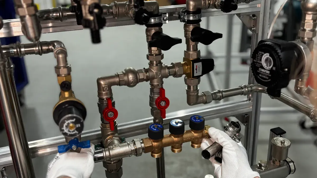
You control flow with a digital control valve by sending exact signals from a digital controller to the valve actuator. The actuator then moves the valve to set the flow rate. This gives you results that are accurate and repeatable.
This guide walks you through setup, operation, and troubleshooting step by step. You will learn how to get easy and reliable flow control. The process is practical and simple. With the right approach, you can master your flow control valve and keep your system running smoothly.
Key Takeaways
- Digital control valves use clear signals to control flow in a steady and reliable way.
- Getting it right means wiring it correctly, calibrating it, and setting up the controller.
- Adjusting the control loop and picking the right flow feature make it more accurate.
- Doing regular maintenance and fixing problems keeps your valve reliable and working well.
- Digital valves save energy and work well in hydraulic systems that use pressure compensation.
Understanding Digital Control Valve Basics
A digital control valve is a motor-driven or solenoid-operated device. It provides precise flow rate control and batch delivery. You send a signal from your controller, and the valve adjusts its position to match your target flow. This creates a reliable process control loop for your system.
Key Components and How They Work
Every digital control valve contains four main parts. The valve body holds the internal trim and directs fluid through the system. The actuator moves the valve stem. You can choose a pneumatic diaphragm, pneumatic piston, or electric motor actuator based on your application needs. The positioner reads the controller output signal and adjusts the stem to the correct position. The digital controller manages the entire operation and communicates your setpoint to the valve.
The valve body material must match your process conditions. Common options include:
- Carbon steel (ASTM A216 WCB) for general non-corrosive service
- Low-temperature steel (ASTM A352 LCB) for cryogenic applications
- Chrome moly alloys (ASTM A217 WC6/WC9) for high-temperature steam
- Stainless steel (CF8, CF8M) for corrosive chemical environments
- Duplex stainless steel (2205) for seawater service
Digital vs. Analog Control Valves
Digital valves outperform analog designs in energy efficiency. They eliminate throttling losses found in traditional proportional valves. These systems can further reduce energy consumption by 30–50% compared to conventional designs by controlling flow generation rather than flow restriction.
A pressure-compensated flow control valve maintains steady flow regardless of load changes. Digital versions of these valves respond faster and hold tighter tolerances. Your hydraulic system benefits from lower leak rates when using poppet-type digital valves. This avoids energy waste from fluid loss.
Setting Up Your Electronic Flow Control Valve
Good setup makes sure your valve works right from the first day. Follow these steps to install and set up your system the right way.
Installation and Wiring Essentials
First, check that your valve fits the process conditions. Compare the body material, pressure class, and temperature range with your application.
Mount the valve in your pipeline with the flow arrow pointing downstream. Support the piping on both sides so the valve body does not get stressed. Leave enough room for the actuator to move and for future maintenance access.
Wire the actuator and controller based on your signal type. Use shielded cable for analog signals to cut down electrical noise. Connect the positioner feedback wiring if your system tracks position.
For pneumatic actuators, hook up the air supply line and set the regulator to the pressure shown on the actuator nameplate. Add a filter-regulator to keep the air clean and dry. For electric actuators, check that the supply voltage matches the motor rating before you power the unit.
Configuring the Digital Controller
Setup starts with choosing your input signal type. Match the controller output signal to the valve positioner input. Pick 4–20 mA for standard analog control, or choose a digital protocol for networked systems.
Next, calibrate the valve position. Set the zero point with the valve fully closed and the span point with the valve fully open. This step makes sure the positioner reads the stem position correctly across the full travel range.
Set up your communication protocol if you use HART, Modbus, or Profibus. Assign the right address and check that the controller gets feedback from the positioner. Test the loop by sending a few setpoint changes and watching how the valve responds.
A well-configured flow control valve responds smoothly to every command. Take time during setup to check each connection and setting. This effort pays off with reliable flow control for years of operation.
Operating and Adjusting Flow
After your valve is set up, you need to run it and make changes. This step turns a good installation into a flow control system you can trust.
Setting Parameters and Control Valve Flow Characteristics
Begin by typing your target flow rate into the digital controller. This number becomes the set point for the flow rate. The controller compares this target to the real flow and changes the output signal to the valve.
Then, tune the control loop. PID tuning changes how the controller reacts to errors. The proportional term reacts to the current error. The integral term fixes errors that build up over time. The derivative term guesses future errors. Good loop tuning keeps the flow steady with no shaking. Bad loop tuning causes hunting or slow response.
Picking the right control valve flow characteristics matters for accurate flow rate control. You have three main choices. A linear control valve flow characteristic changes flow in direct proportion to valve travel. An equal percentage characteristic changes flow slowly at first, then faster as the valve opens. A quick opening characteristic gives maximum flow with very little travel.
The inherent control valve flow characteristics describe how the valve acts with steady pressure drop. The installed control valve characteristic shows how the valve really works in your system. These two differ because system pressure drop changes with flow.
Equal percentage gives clear benefits for many applications:
- Excellent rangeability handles a wide flow range from very low to high capacities.
- Better low-flow control keeps precise regulation even at small openings.
- Strong real plant adaptability copes well with changing pressure drops and shifting process loads.
- Suitable for temperature and pressure control gives smooth response across load changes.
When pipe and equipment losses rise a lot with flow, the pressure drop across the valve falls. Equal percentage creates a more nearly linear installed characteristic in this case. When a linear inherent characteristic makes too much installed gain at low load, equal percentage avoids saturation and instability.
Using Feedback for Precise Adjustments
Feedback signals let you watch valve position and flow in real time. A position transmitter reports where the valve stem sits. A differential pressure transmitter measures the pressure drop across the orifice. Together, these signals confirm that the valve reaches your desired flow.
Use this feedback to make small corrections. If the flow drifts from your target, check the positioner reading first. A mismatch between command and position suggests calibration drift. Recalibrate the positioner to bring back accurate flow rate control.
The valve features a guided trim design that reduces noise and cavitation while providing high capacity. This improves flow control accuracy and makes trim last longer. For hydraulic systems, a pressure-compensated flow control valve keeps flow steady no matter how the load changes. Digital versions respond faster and hold tighter tolerances.
Troubleshooting Common Flow Control Valve Issues
When your valve stops working, follow a clear plan. First do the simple checks. Then move to the harder ones.
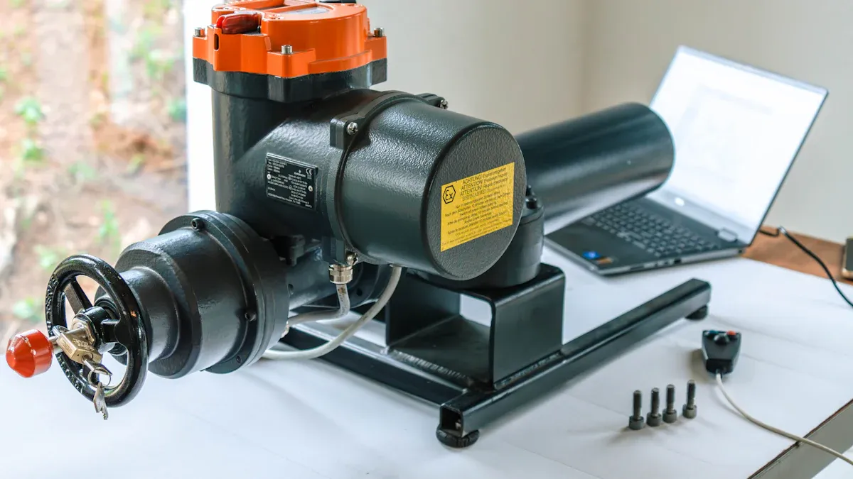
Valve Is Not Responding
First, check the power supply. Measure the voltage at the controller terminals. The table below shows the right voltage ranges for different conditions.
| Operating Condition | Minimum Voltage | Maximum Voltage |
|---|---|---|
| Analog control (hardware v2+) | 9.5 VDC | 30 VDC |
| HART communication (hardware v2+) | 10 VDC | 30 VDC |
| Analog control (hardware v1) | 10.5 VDC | 30 VDC |
| HART communication (hardware v1) | 11 VDC | 30 VDC |
| Multi-drop topology | 11 VDC | 30 VDC |
Industry best practices say to keep the instrument terminal voltages at least 15–20% above the minimum values. This ensures reliable operation in worst-case situations, like long cables, extreme temperatures, and busy HART communication.
For loop power checks, the DVC6200 specs suggest an impedance of 500 to 550 ohms. That equals about 10 to 11 volts at 20 mA. If voltage is correct, check the controller output signal wiring. Look for loose connections or broken wires. Next, check the actuator air supply for pneumatic valves. Low air pressure stops the actuator from moving the valve stem. Finally, review your controller settings. A wrong setpoint or a disabled output will stop the valve from responding.
Flow Rate Is Inaccurate or Unstable
First, recalibrate the positioner. Positioner drift makes the valve miss its target. Check for cavitation or flashing in liquid service. Cavitation happens when local static pressure drops below saturated vapor pressure. This creates vapor bubbles that collapse hard and damage valve parts. A noisy valve in liquid service is usually cavitating. Early cavitation sounds like sand going through the valve. Bad cavitation makes rough noise and causes damage.
Check your loop tuning settings. Poor tuning causes hunting or slow response. Inspect the trim for wear. Worn trim changes the flow characteristic and lowers accuracy. For hydraulic systems, a pressure-compensated flow control valve keeps flow steady no matter how load changes. Digital versions respond faster and hold tighter tolerances.
Their global support network helps you solve problems quickly.
Best Practices for Easy Flow Control
Routine Maintenance for Longevity
A simple maintenance plan keeps your flow control valve running for many years. Check the actuator every three months. Look for air leaks on pneumatic units and listen for strange motor sounds on electric units. Clean the trim during planned shutdowns. Use mild dish soap in warm water for common dirt and light oils. For mineral buildup, soak the dirty parts in a weak white vinegar mix for a short time. Rinse well after. Stay away from rough brushes that scratch plastic seats.
Check calibration after each cleaning. Compare the positioner reading with your controller output. Look for leaks at all connections. Tighten fittings and swap out worn gaskets when needed. This routine stops small problems from turning into big breakdowns.
Optimizing for Precision and Efficiency
Pick the right control valve flow characteristics for your use. Equal percentage works well for most temperature and pressure control loops. Linear fits liquid level control. Quick opening suits on-off batch delivery.
Digital diagnostics move maintenance from reactive to predictive, reducing unplanned downtime. These systems spot calibration drift, sensor fouling, and mechanical wear before they cause failure.
Tune your loop tuning settings to match your process patterns. A pressure-compensated flow control valve keeps a steady flow rate no matter how the load changes in hydraulic systems. Digital versions react faster and hold tighter tolerances. Check your pressure drop across the valve often. High pressure drop wastes energy and leads to cavitation.
You can control flow with confidence once you understand the basics of a digital control valve system. You learned how each key part works, how to set up the electronic flow control valve, and how to run the controller for flow control. Troubleshooting steps help you fix common problems fast. These skills keep your system running smoothly every day.
Setting the right flow rate keeps your process running well. Steady flow gives you precision and ease. The whole process is simple when you follow these steps.
You have the knowledge to manage your valve system well. You can handle any changes your process needs.
FAQ
How do you choose actuator types for flow control?
If your area has dangerous conditions, use a pneumatic actuator. If your plant is far away and has no air supply, pick an electric actuator. Both types position the valve exactly. This keeps flow steady and lowers flow changes.
What does cage-guided trim improve in your valve?
Cage-guided trim guides the plug and shapes the path of flow. This cuts noise, stops cavitation, and makes trim last longer. Your valve gives more accurate flow with less wear. The steady flow path boosts repeatability.
How do you select the right flow characteristic?
Pick linear for liquid level control. Choose equal percentage for temperature and pressure loops. Use quick opening for batch delivery. The right characteristic keeps your flow rate stable and improves overall flow. Your valve gives precise control.
What maintenance keeps your valve reliable long-term?
Check the actuator every three months for air leaks or odd motor sounds. Clean the trim during shutdowns. Recalibrate the positioner. This routine keeps accurate flow rate control. Your valve runs reliably for years.
Can a digital control valve work in a hydraulic system?
Yes. A pressure-compensated flow control valve keeps flow steady no matter how the load changes. Digital versions respond faster and hold tighter tolerances than analog designs. This makes them perfect for hydraulic uses that need precise flow rate regulation.