Ever wonder how automated factories or HVAC systems control flow so well without a person turning a wheel? That is what a motorized control valve does. This device uses an electric actuator to control flow rate, pressure, or temperature on its own. You see these valves all over modern industry. The global motorized control valve market hit USD 11.45 billion in 2024 and will grow 6.28% each year to USD 18.63 billion by 2032. You need to know what a motorized valve is, its main parts, and how it works step-by-step. This knowledge helps you pick the right equipment for your pressure and flow control needs.
Key Takeaways
- A motorized control valve uses an electric actuator to automatically control flow, pressure, or temperature.
- The actuator gets a signal, and a motor moves the valve stem to change the flow passage.
- You can pick on/off valves for simple shutoff, or modulating valves for exact control.
- Getting the right size is key for steady performance and lower energy costs.
- Motorized valves give you automation, remote control, and safety benefits that manual valves do not have.
What Is a Motorized Valve? Understanding the Basics
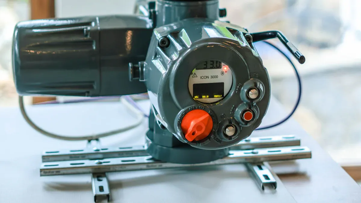
A motorized valve pairs a valve body with an electric actuator. The valve body sits inside your pipe and touches the fluid. The actuator is mounted on top and gives the force to move the valve. This pairing creates a motorized valve system that obeys electrical commands. You get a valve with an electric actuator that can automatically open, close, or control flow without anyone turning a handwheel.
Precise Flow Control with an Actuator
The electric actuator acts as the muscle of the operation. It gets a control signal from your system and changes that signal into mechanical movement. A motor inside the actuator spins, and a gear train slows down the speed while boosting force. For rotary valves, the gears turn the stem 90 degrees. For linear valves, the gears change spinning motion into pushing force. This mechanical advantage lets a small actuator handle high fluid pressure.
The actuator allows two main types of control. A modulating motorized valve changes flow from 0 to 100 percent using analog signals. A 4-20 mA signal gives proportional control, where 4 mA means fully closed and 20 mA means fully open. An on-off motorized valve uses on/off logic instead. It moves to fully open or fully closed positions with no in-between. You use on-off control for isolation and batch sequencing. You use modulating control for process regulation where you need to control flow, pressure, or temperature exactly.
Key Characteristics of a Motorized Control Valve
A motorized control valve has abilities that manual valves cannot match. Here are the main differences between modulating and on-off designs:
| Aspect | On/Off Motorized Valve | Modulating Motorized Valve |
|---|---|---|
| Operating logic | Only fully open or fully closed | Moves to intermediate positions as needed |
| Control capability | Controls whether flow exists | Adjusts flow according to demand |
| Temperature control | Coarser control with fluctuations | More precise and stable management |
| Typical applications | Fan coil systems, simple zone control | AHU coils, heat exchanger circuits |
| Advantages | Simpler logic, lower cost | Precise flow control, stable temperature |
| Disadvantages | Coarser control, frequent switching | Higher initial investment |
Your choice between these designs affects performance a lot. A modulating valve gives active feedback and tells you its position in between. An on-off valve gives passive feedback only when fully open or fully closed. Using the wrong type for your job can cause it to break early. An on-off valve used for adjusting pressure may overheat because its motor is not made for frequent movement.
The motorized control valve also relies on rangeability, deadband, hysteresis, and response time for good performance. These characteristics determine how well your valve follows the setpoint and keeps steady automatic control. A good match of valve and actuator gives reliable automated flow control across your whole process.
How Does a Motorized Valve Work? A Step-by-Step Guide
To understand how a motorized valve works, you follow the signal from your control system through the actuator to the final flow adjustment. The process turns electrical energy into mechanical motion, step by step. Each motorized valve uses an electric actuator to receive commands, move the stem, and control flow on its own.
Signal Reception and Motor Activation
Your control system sends a control signal to the electric actuator. For modulating control, this signal is usually a 4-20 mA current. The actuator has a positioner that reads this signal. The positioner compares it with the actual position feedback from the valve. The gap between the setpoint and the actual position is the error signal. The positioner uses this error to decide how much the motor must turn. This keeps the valve accurate. The positioner then tells the motor to start moving.
| Aspect | Analog (Electro-Pneumatic) | Digital |
|---|---|---|
| Input Signal | 4-20 mA or 0-10 VDC (analog) | 4-20 mA, HART, PROFIBUS, Foundation Fieldbus |
| Conversion | Converts electric signal to pneumatic signal via I/P transducer | Uses microprocessor to convert signal and perform position control |
| Mechanism | Mechanical beam, cam, and flapper assembly | Microprocessor-based |
Digital valve positioners can do more than older analog designs. They get a 4-20 mA analog signal as the control signal. This analog current level is the position demand. HART digital communication rides on the same wires. This lets digital data travel for better accuracy and stability. The positioner reads both the analog signal for position control and the digital HART protocol for diagnostics. Pressure changes in the system can affect performance. The positioner adjusts for these pressure changes to keep control precise.
The positioner sends power to the motor. The motor starts spinning and turns electrical power into mechanical movement. The motor is usually a small AC or DC unit that runs at several thousand revolutions per minute.
The Role of the Gear Train and Stem Movement
The motor is usually a reversible, high speed type connected through a gear train to reduce the motor speed and thereby increase the torque at the stem.
In an electric actuator, the motor runs at high speed but low force. The gear train cuts this speed and raises output torque. Common gear types include worm gears, spur gears, and planetary gears. The gear ratio sets how much the speed drops and how much the torque rises. A ratio of 50:1 means the output turns once for every 50 motor revolutions, multiplying the torque by roughly 50 times. This mechanical advantage lets a small motor move the valve stem against high line pressure.
The pressure differential across the plug creates a large force that resists movement. The pressure rating of the valve sets the required actuator force. You must match the actuator size to the maximum pressure drop expected in your system. A larger differential needs more torque from the actuator. This sequence defines how a motorized control valve operates. The gear train multiplies torque to overcome the load.
The valve stem rotates for a ball valve or pushes linearly for a globe valve. As the stem moves, the flow passage changes size. This controls fluid flow through the valve. The positioner constantly checks position feedback from the actuator. It reads the stem position from a potentiometer or encoder inside the actuator. The positioner compares this value against the control signal. If the actual position does not match the demand, it sends more power to fix the error. If a difference exists, the positioner adjusts the motor direction and speed until the error is gone. This continuous feedback loop keeps positioning accurate down to fractions of a millimeter.
For advanced applications, the TANGGONG control valve offers pneumatic, electric, and hydraulic actuator options. These give precise stem positioning under demanding conditions. A modulating motorized valve holds any intermediate position. An on-off motorized valve only uses feedback for fully open or fully closed. The feedback signal also reports valve status to the main controller. This allows automated flow control without human operators. The combination of accurate feedback and robust gearing ensures reliable operation over thousands of cycles.
Key Parts of a Motorized Control Valve
A motorized valve has two main parts. These are the actuator and the valve body. They work together to control flow in your pipe.
The Electric Actuator and Positioner
The actuator gives the force. An electric actuator has a motor, gear train, limit switches, and torque switches. Limit switches show the open or closed position. Torque switches keep the valve safe from high pressure. A manual override lets you turn the valve by hand when power goes out.
The positioner works like the brain. It gets a control signal. A digital positioner does more than an old analog one. It keeps deadband at about 0.5% of span. It works with HART or Profibus protocols. These give you steady position feedback and advanced diagnostics. The positioner needs position feedback to work. It uses this data to adjust the valve. The feedback loop keeps control accurate. This gives you steady feedback for precise automated control.
TANGGONG control valves use these advanced parts. They have cage-guided trim for low noise and steady operation. They work with 4-20 mA, HART, and Profibus signals. You get precise digital control for your process.
Valve Body Types: Ball, Butterfly, and Globe
The valve body touches the fluid. Three common types of motorized valves are ball, butterfly, and globe.
A globe valve is best for throttling. The plug moves toward the seat in a straight line. This allows fine, repeatable flow changes. You use a globe valve for pressure management and steam control. The fluid changes direction inside the body. This causes a higher pressure drop.
A ball valve is best for tight shut-off and low pressure drop. The ball turns 90 degrees. The flow is either on or off. You should not use a ball valve for throttling.
A butterfly valve is best for large pipes. It uses a turning disc. It has a moderate pressure drop. The smooth path offers lower pressure resistance.
TANGGONG offers all these body types. An on-off motorized valve often uses a ball or butterfly body for fast isolation. A modulating valve uses a globe body for precise fluid flow control. The actuator gives steady feedback to the controller. This reliable feedback is key for automated process control.
How to Select the Right Motorized Valve
Motorized Control Valve vs. Manual Valves
Manual valves need a person to turn a wheel or handle. A motorized valve uses an electric actuator to do the work. This difference changes everything about how you operate. With a motorized control valve, you get automation, remote control, and precision. You no longer send workers into dangerous areas to adjust flow. You send a signal instead.
The advantages of motorized valves show up in the numbers. Automated systems place bags at rates up to 40 per minute with 99.5% accuracy. Vision-guided tooling cuts overfills by up to 50%. Injury rates drop by as much as 75%. One chemical client reduced waste by 40% and saved over $250,000 a year. Replacing manual valves with automated control valves can improve chiller performance by up to 30% and reduce pump energy consumption by up to 80%. A retrofit with 15 automated valves cut chilled water pumping by 49%, saving about $23,000 each year. These gains come from steady control and no human error.
Key Applications and Selection Factors
You find motorized valves in petrochemical plants, water treatment facilities, and power generation stations. Each industry needs precise fluid flow control. Petrochemical plants handle harsh chemicals and high pressure. Water treatment plants must meet exact flow requirements. Power stations deal with extreme temperatures.
Proper sizing is the most important selection factor. You need the right Cv or Kv value for your process. Cv measures water flow in gallons per minute at 60°F with a 1 psi pressure drop. Kv uses cubic meters per hour at 20°C with a 1 bar pressure drop. The two convert simply: Kv = 0.865 × Cv. If Kv is too low, your valve stays near 100% open and cannot supply enough flow. If Kv is too high, the valve operates at very low openings with poor controllability.
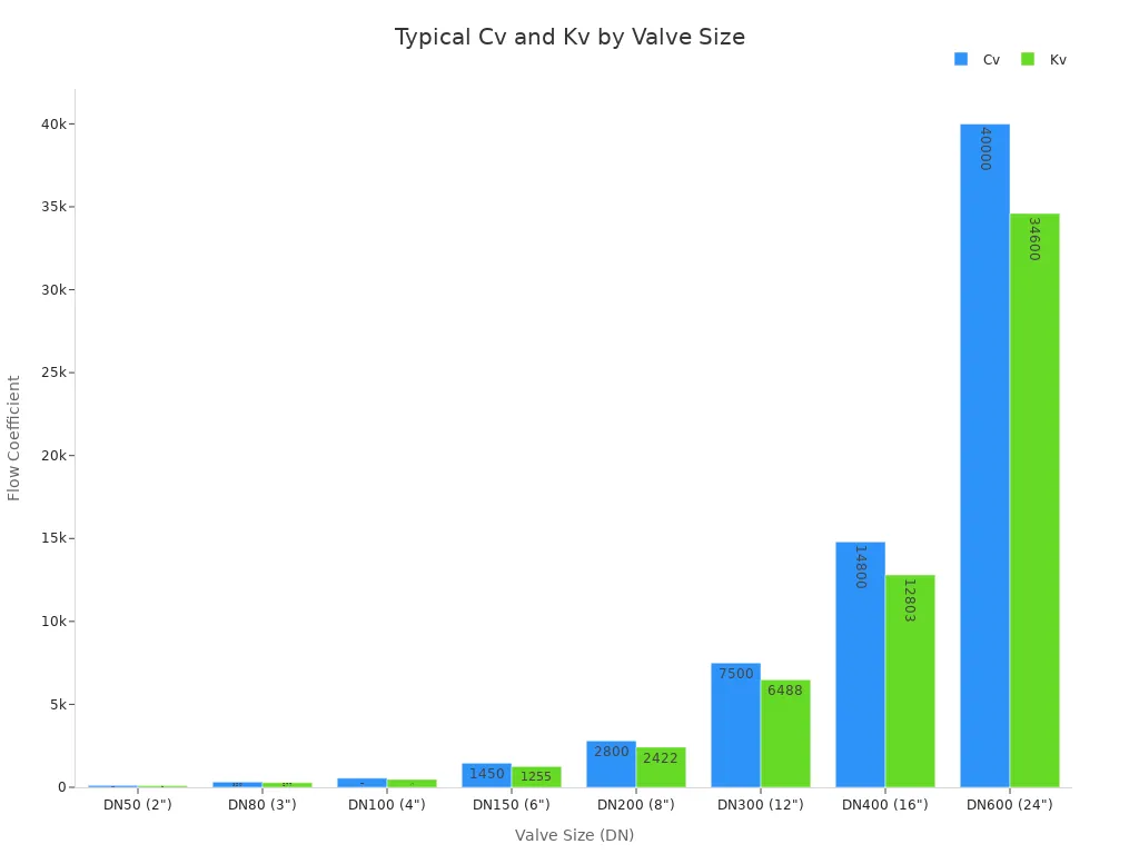
TANGGONG offers free IEC 60534-compliant valve sizing consultations. This service helps you select the correct valve for your specific process. Correct sizing ensures long-term reliability and efficiency. You avoid water hammer, cavitation, and excessive energy use. An on-off motorized valve works for simple isolation. A modulating valve with position feedback gives you precise control. The actuator you choose must match your pressure and flow needs.
A motorized control valve joins a valve body with an electric actuator to control flow, pressure, or temperature on its own. The process follows a clear path: a controller sends a signal, the motor spins, the actuator turns that motion into stem movement, and the valve changes the flow passage. Picking a trusted partner matters just as much as picking the right design. TANGGONG Valve Group provides engineered solutions with global certifications, including SIL-capable designs per IEC 61508 and IEC 61511, plus free sizing help. Check out their motorized valve product lines for your next project.
FAQ
What is the difference between a control valve and a shut-off valve?
A control valve changes flow all the time to keep a process steady. A shut-off valve only opens all the way or closes all the way to block flow. You use a motorized valve with modulating control to regulate flow. You use a shut-off valve when you need a tight seal when it is fully closed.
What is the difference between pneumatic and electric actuators?
Pneumatic actuators use compressed air and respond fast, so they work well in dangerous areas. Electric actuators use a motor to position the valve precisely. You pick electric when you have no air supply or need to control it from far away. Both work well for high pressure jobs.
What is cage-guided trim in control valves?
Cage-guided trim uses a round cage with small precision holes to guide the plug. This design cuts down noise and stops cavitation. It also makes the trim last longer under high pressure. TANGGONG control valves use this trim for steady performance.
How do I size a control valve for my application?
Sizing needs fluid properties, flow rate range, upstream and downstream pressure, temperature, and allowed pressure drop. TANGGONG offers free IEC 60534-compliant sizing help. Getting the size right ensures reliable control and avoids problems like cavitation or wasted energy.
What certifications do TANGGONG control valves have?
TANGGONG control valves carry ISO 9001:2015, CE, and SGS certifications. They meet ANSI/FCI 70-2 shutoff standards. SIL-capable designs per IEC 61508 are also available. You can also ask for third-party inspections by TUV, SGS, or DNV for your project.