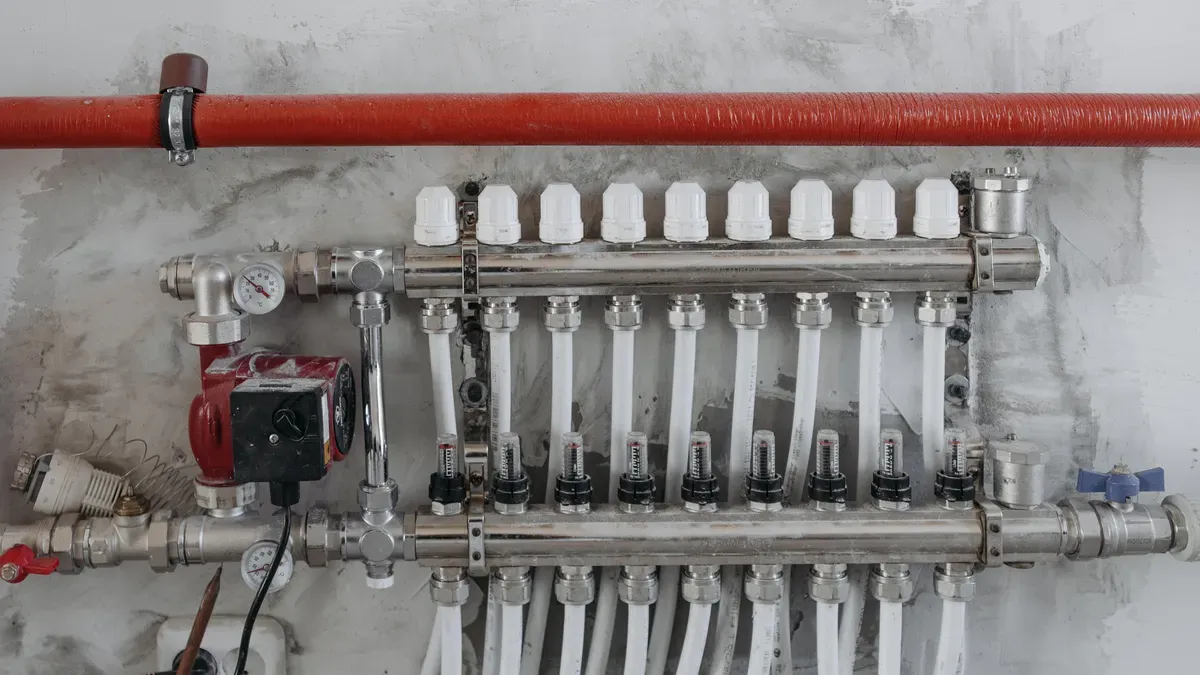
From construction equipment to car brakes, hydraulic power drives many machines. Hydraulic control valve systems manage this power for exact operation. Professional engineers group the main hydraulic control valve types into three categories: directional, pressure, and flow control. Understanding these hydraulic valve types, also known as control valve types, is the basis of hydraulic knowledge. A large and growing market supports these parts. According to research firm Fact.MR, the global hydraulic valve market will reach US$ 5.89 billion in 2024 with a CAGR of 3.8%. These valves act like traffic cops: they direct flow, regulate force, and control speed. This guide explains these hydraulic control valve types in simple terms. Anyone, no matter their technical background, can grasp the core ideas.
Key Takeaways
- Hydraulic control valves control the flow, pressure, and speed of fluid in machines.
- There are three main types: directional, pressure, and flow control valves.
- Directional valves direct the flow of fluid to start, stop, or change direction.
- Pressure valves keep force at safe levels to protect equipment.
- Flow valves control how fast actuators move, helping them run smoothly and exactly.
- Check valves let fluid flow only one way, so backflow doesn’t cause damage.
- Relief valves open to release extra pressure and stop bursts.
- Picking the right valve keeps things safe, works well, and lasts a long time.
What Is a Hydraulic Control Valve?
A hydraulic control valve is a mechanical device that controls how fluid moves inside a hydraulic system. Think of it like a faucet in a kitchen. A person turns the handle to start, stop, or adjust the water. A hydraulic control valve does the same job for hydraulic fluid. It sits between the pump and the moving parts of a machine. The pump makes force, but the valve decides where that force goes and how much of it gets there. Without this control, a hydraulic system would push fluid everywhere at full power. That would waste energy and damage equipment.
Key Hydraulic Control Valve Functions
Every hydraulic control valve does one or more of three main tasks. These hydraulic control valve functions keep a system balanced and predictable. The three main functions are:
- Direction control: controlling the path that fluid takes through the hydraulic system
- Pressure control: managing the force made by the fluid within the circuit
- Flow rate control: controlling the amount of fluid moving through the system per unit time
Each function has its own job. Direction control decides which cylinder or motor gets fluid. Pressure control keeps the force within safe limits. Flow rate control sets how fast a cylinder extends or a motor spins. A single machine may use several hydraulic control valve designs to handle all three jobs at once. Engineers pick the right valve for each task based on the operating pressure and the speed the machine needs.
Why These Valves Matter
Hydraulic valves protect both people and equipment. A pump can make a huge amount of force. That force has to go somewhere. A relief valve opens when pressure gets too high. It sends fluid back to the tank instead of letting a hose burst. This safety feature stops injuries and costly breakdowns. Valves also make systems work better. They send fluid only where the machine needs it. The pump then uses less energy to do the same work. A well-controlled system runs cooler and lasts longer.
These devices also give operators exact control. A crane can lift a heavy load slowly and stop it right where needed. A excavator can swing its arm with smooth, steady motion. None of that would happen without valves directing and limiting the fluid. In short, hydraulic control valves turn raw pump power into useful, safe, and repeatable motion. They are the quiet heroes behind almost every hydraulic machine on a job site or factory floor.
The Three Main Hydraulic Valve Types
Directional, Pressure, and Flow
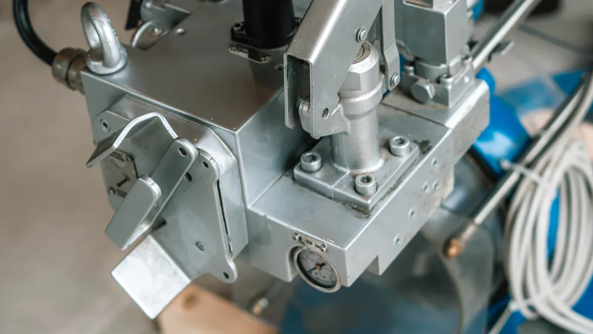
Experts sort the three main hydraulic control valve types by what they do. Each type does a certain job, like different tools in a toolbox. A wrench cannot hammer a nail, and a hammer cannot turn a bolt. In the same way, each hydraulic valve type handles one main function. Because there are different types, a machine often uses several control valve types at once. A directional valve controls the start, stop, and direction of fluid flow. A pressure valve keeps pressure at safe levels. A flow valve controls how fast fluid moves to set actuator speed. Each group has its own purpose, and no single type can do another’s job. A good system uses all three to run smoothly, safely, and well. Every part works together, but the valve choice decides how the machine acts.
Directional control valves work like a traffic cop at a busy intersection. This type decides which path the fluid takes through the system. When a forklift driver pulls a lever, a directional valve sends fluid to the lift cylinder. The fluid then flows to a cylinder, motor, or other actuator and makes motion. Without this part, the machine cannot move the way it should. Every hydraulic system needs directional control valves to start, stop, and reverse motion. Common examples include spool and check types. A spool valve slides inside a body to open or close different passages. This simple action makes complex motion possible in many machines. Forklifts, excavators, and presses all depend on these parts for basic movement.
Pressure control valves work like a safety relief device on a water heater. This type keeps the system pressure within safe limits. If pressure gets too high, the valve opens and sends extra fluid back to the tank. This action stops damage to hoses, seals, and other parts. A typical relief valve opens at a set pressure, often set by a spring. Pressure control valves also keep steady pressure for sensitive parts of the machine. For example, a reducing valve can lower pressure for a clamping circuit that needs less force than the main system. Relief and reducing types are two common pressure control groups. Their role is very important for safety and equipment protection. Without these devices, a hydraulic system could fail badly during operation.
Flow control valves work like a speed limit sign for the fluid. This type controls how fast the fluid moves through the system. A slower flow rate means a cylinder extends more slowly, which helps during precise positioning. A faster flow rate allows quicker movement, useful for rapid cycling. Operators use flow control valves to match the speed of a machine to the task at hand. A common design is a needle valve, which adjusts the size of the passage. Turning a handle changes the opening and alters the flow rate. This valve type improves precision and safety during operation by stopping sudden, jerky motion. In manufacturing equipment, flow control valves let operators set consistent cycle times.
Knowing these hydraulic valves helps operators pick the right part for a certain task. These three hydraulic valve types form a complete control system. Each hydraulic control valve type has its own purpose, and they work as a team. A machine often uses all three control valve types at once to lift, lower, swing, and stop with smooth, predictable motion. Picking the wrong valve type can lead to poor performance or even system failure. So, knowing these basic groups gives any operator or technician a solid base for troubleshooting and choosing equipment.
Directional Control Valves
Directional control valves guide where hydraulic fluid goes in a system. These valves work like a traffic cop at a busy crossing. They send fluid to the right actuator at the proper time. Without this part, a machine cannot start, stop, or reverse motion. Two main sub-types exist in this group: a check valve and a spool valve. Each one has its own job. Knowing these hydraulic valve types helps operators pick the correct part for each task.
Check Valves: One-Way Flow
A check valve lets fluid move only one way. It stops reverse flow on its own. A common comparison is a heart valve. It lets blood go forward but stops it from going back. This simple role is very important in hydraulic circuits. A check valve guards pumps from backflow damage and holds loads in place. But these directional control valves can break. Common failure types include backflow failure, leakage, and seat wear. Dirt stuck in the seat causes about 10% of failures in poorly kept systems. Lower-quality products show leakage within the first five years for about 15% of users. Seat wear rates can reach up to 20% in high-use environments. Signs of a failing check valve include cylinder drifting, slow boom drop, jerky movement, and hydraulic overheating. Operators should look for these signs often. A check valve is one type of poppet-style directional valve.
Spool Valves: Multi-Path Control
A spool valve gives the system more control over flow direction. A spool slides inside a body to open or close different passages. This action sends fluid to different parts of the system. A good comparison is a railroad switch. It guides a train onto one track or another. The spool moves to change the flow path. Engineers describe these directional valves by their number of ports and positions. Common setups include a 4/3 valve and a 5/2 valve. A 4/3 valve uses ports called P, T, A, and B. The three positions allow forward, neutral, and reverse flow. Spool-type directional valves come in many types, each for a specific job. The chart below shows a comparison of common spool valve setups.
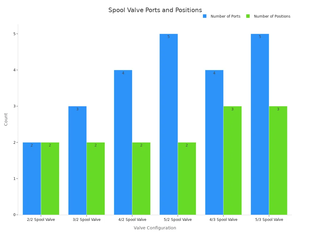
A spool valve also differs by center type, spool action, and control method. Spool-type directional valves need careful choice based on pump type. An open-center design lets fluid return to the tank in neutral. A closed-center design blocks all ports in neutral. A tandem-center design balances speed with response. A spring-centered design returns to neutral when let go. A detent design locks in place. These are examples of spool-type directional valves. This variety lets engineers match the valve to the specific machine. These hydraulic valves form the core of most mobile and industrial equipment.
Pressure Control Valves
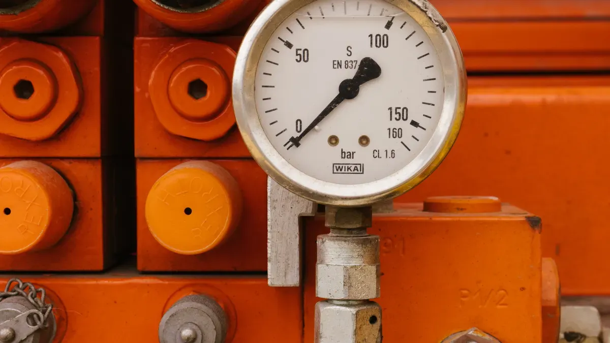
Pressure control valves handle the force of hydraulic fluid in a system. They act like a safety valve on a water heater. That device opens when pressure gets too high. It lets steam out to stop a dangerous burst. Hydraulic systems face the same danger. A pump keeps pushing fluid, and pressure can rise above safe limits. These valves guard the system. They keep force at a level that hoses, seals, and cylinders can handle. Two main types do this job: relief valves and reducing valves. Each one has its own role in protecting equipment and keeping operation steady.
Relief Valves: The Safety Net
Relief valves open to let out extra pressure. They stay closed when the system runs normally. When pressure reaches a set point, the valve opens and sends fluid back to the tank. This stops pressure from rising more. Think of a pressure cooker. Its safety valve lets steam escape when pressure inside gets too high. A hydraulic relief valve does the same for fluid power. These valves stop damage to pumps, hoses, and cylinders. They also protect operators from harm caused by burst lines or flying parts.
The cracking pressure setting is very important. Hydraulic power units usually set the main system relief valve 10 to 15 percent above working pressure. On a 3000 psi log splitter, the relief valve cracks at about 3300 psi. This margin protects the pump and cylinder seals. According to Viking Pump, users can set cracking pressure 10 to 15 percent above the maximum differential pressure for pumps with internal relief valves. For pumps with return-to-tank valves or in-line system valves, the setting goes above the maximum discharge pressure. Standard pressure ratings for these valves reach up to 5000 PSI across several models. The table below shows common pressure ratings.
| Valve Model | Pressure Rating |
|---|---|
| Pressure Relief (Proportional Valves) | Up to 5000 PSI |
| VER03M Direct Operated Pressure Relief | Up to 5000 PSI (5 pressure control ranges) |
| VER03MP Pilot Operated Pressure Relief | Up to 5000 PSI (5 pressure control ranges) |
| VEP03MSV and VEP05MSV 3-Way Pilot Operated Pressure Reducing Valves | Up to 4600 PSI |
Reducing Valves: Keeping It Steady
Pressure reducing valves lower pressure to a safe level for certain parts of a circuit. They work like a water pressure regulator in a house. That device takes high incoming pressure and gives a steady, lower pressure to the faucets. A hydraulic reducing valve does the same for one branch of the system. It installs in-line where pressure reduction is needed. The valve adjusts continuously during normal operation. It changes its opening in response to upstream flow and pressure changes. This keeps downstream pressure consistent.
These valves differ from relief valves in function and design. A pressure relief valve works as a safety device. It stays normally closed and opens only when pressure goes above the set point. A pressure reducing valve works as a control device. It stays normally open and throttles flow to keep lower downstream pressure. Relief valves install in parallel to the main flow path. Reducing valves install in-line. Relief valves fail open to allow pressure release. Reducing valves fail closed or hold their last position. Both types serve key roles. Relief valves protect the whole system from overpressure. Reducing valves serve circuit sections that need lower pressure. Together, they keep hydraulic valves working within a safe operating pressure range.
Flow Control Valves & TANGGONG VALVE
How Flow Valves Control Speed
Flow control valves control how fast hydraulic fluid moves through a system. They work like a faucet that someone opens or closes to adjust water flow. When the valve opening gets smaller, less fluid goes through. A cylinder then moves out more slowly. When the opening gets bigger, fluid moves faster and the cylinder moves out quickly. This simple action gives operators exact control over machine movement.
Two main designs exist among flow control valves. A needle valve uses a tapered stem that screws into a seat. Turning the handle changes the gap and changes the flow rate. A pressure-compensated flow control valve does even more. It keeps a steady flow no matter how the load changes. A spring-loaded compensator spool adjusts the opening to keep constant pressure across the control orifice. This design works well for cylinder speed control and machine tool feeds.
TANGGONG Control Valves
TANGGONG VALVE is a leading maker of control valves for industrial use. The company builds hydraulic control valve designs that give precise adjustment in demanding applications. Their proportional control valves and other control valve types serve industries such as oil and gas, chemical processing, and power generation.
At TangGong, every valve we deliver is built around consistent performance standards and high reliability. … Our quality control system runs through the entire production process. … TangGong valves are widely applied in core industries including oil & gas, chemical processing, power generation, water treatment, or other critical pipeline systems. … Today, TangGong products are exported to over 20 countries and regions, including Europe, North America, the Middle East, and Southeast Asia. Behind this global footprint is consistent quality control and engineering-driven manufacturing.
TANGGONG control valves feature cage-guided trim for low noise and anti-cavitation. The cage surrounds and guides the valve plug, which reduces vibration and keeps stability under high pressure drops. This design also provides high capacity and excellent flow control. The company offers free sizing consultations and complies with international standards like IEC 60534 and ANSI/FCI 70-2. Their proportional valves and compensated flow control valves meet the needs of modern automated systems. For industrial control valve solutions, explore the TANGGONG control valve series at https://www.tg-valves.com/category/control-valve-series.
Your Hydraulic Control Valve Guide
This part sums up the three main hydraulic valve types in one place. Directional control valves send fluid along chosen paths. Pressure control valves keep force within safe limits. Flow control valves set actuator speed by adjusting how much fluid moves. Each type has its own job. Together they make a full hydraulic control system. This guide gives operators and technicians the basics they need to understand fluid power.
Picking the right hydraulic valve type takes close attention to several things. The table below lists key points for valve selection in industrial work.
| Factor | Key Consideration |
|---|---|
| Flow Capacity | Valves must handle peak flow with a small pressure drop. A too-small valve causes waste and heat. |
| Pressure Rating | A valve should rate at least 25% above the highest system pressure for safety and long life. |
| Response Time | Match valve speed to the job. Fast response works for on/off control. Slower response cuts shock loads. |
| Contamination Resistance | Pick spool or poppet types based on how clean the fluid is. Tighter gaps need better filters. |
| Mounting & Integration | Subplate, in-line, or manifold mounting affects space, upkeep, and leaks. |
| Manufacturer Specs | Follow OEM advice to make sure parts fit and warranty stays valid. |
| Application Analysis | Right-size valves for real needs. Do not use theoretical max numbers. |
| System Integration | Think about how valves work with pumps, actuators, and other parts. |
Operators must also check the work environment. Very hot or cold weather affects material choice and seal life. Corrosive conditions need special alloys or coatings. Load sensitivity decides if a simple on/off valve or a proportional valve works better. Maintenance needs also matter. Valves that are easy to service reduce downtime. Part availability affects long-term reliability.
Compatibility with existing parts avoids expensive redesigns. Connection types, port sizes, and operating numbers must match pumps, actuators, and pipes. Talking to valve experts helps when these factors get tricky.
Flow control valves need extra care with fluid thickness and operating temperature. Thicker oil at low temps changes how a valve acts. The actuator’s response accuracy must match the control system needs. Electronic control or remote adjustment adds flexibility but makes design harder. The system pump type, constant flow or variable displacement, also affects valve choice. These details matter for getting smooth and efficient operation.
Relief valves act as the safety net in any system. They open when pressure goes past the set point and send fluid back to the tank. This action protects hoses, seals, and cylinders from harm. Pressure reducing valves lower pressure for certain circuit branches. Both types belong to the pressure control valves group.
TANGGONG VALVE builds control valves for tough industrial use. Their products include cage-guided trim for low noise and anti-cavitation. The valves meet IEC 60534 and ANSI/FCI 70-2 standards. Industries like oil and gas, chemical processing, and power generation use these control valve types for exact adjustment. TANGGONG offers free sizing help and supports engineers through the whole selection process. For industrial valve needs, check the TANGGONG control valve series at https://www.tg-valves.com/category/control-valve-series.
Hydraulic systems depend on three main hydraulic valve types. Directional control valves send fluid down the correct path. Pressure valves keep force inside safe limits. Flow control valves set how fast movement happens. Each type does a different job, but they work as a team. Together they make machines safe, efficient, and powerful.
Readers can now look at a crane, a forklift, or a car brake in a new way. This basic knowledge turns everyday machines into systems anyone can understand. A hydraulic control valve shapes the power behind modern life. These valves deserve thanks for the quiet work they do every day.
FAQ
What does a hydraulic control valve do?
A hydraulic control valve handles how fluid moves inside a hydraulic system. It sends flow, manages pressure, or controls flow rate. Think of it like a traffic cop for hydraulic fluid. It tells fluid where to go, how hard to push, and how fast to move.
What are the three main types of hydraulic valves?
Experts put hydraulic valves into three groups. Directional control valves guide fluid along chosen paths. Pressure valves keep force within safe limits. Flow valves set actuator speed by adjusting fluid movement. Each type has a certain job in the system.
How does a check valve work?
A check valve lets fluid flow in only one direction. It stops reverse flow on its own. A heart valve works the same way. It lets blood go forward but blocks it from going back. This simple design protects pumps and holds loads in place.
What is the difference between relief valves and reducing valves?
Relief valves open to release extra pressure and protect the whole system. Reducing valves lower pressure for certain circuit branches. Relief valves stay normally closed. Reducing valves stay normally open and throttle flow. Both belong to the pressure control group.
How do flow control valves adjust speed?
Flow control valves change the size of the passage for fluid. A smaller opening slows fluid movement. A larger opening speeds it up. Operators turn a handle to adjust the gap. This action gives exact control over cylinder speed and machine motion.
What are proportional control valves used for?
Proportional control valves give precise adjustment in industrial applications. They respond to electrical signals and change their opening continuously. Industries like oil and gas, chemical processing, and power generation use them. TANGGONG VALVE builds these valves with cage-guided trim for low noise.
Why do hydraulic systems need multiple valve types?
No single valve can do every job. A machine needs directional valves to steer fluid, pressure valves to stay safe, and flow valves to set speed. These valves work as a team. Together they make hydraulic systems safe, efficient, and powerful.
How can someone pick the right valve for a machine?
Operators should check flow capacity, pressure rating, and response time. They must match the valve to the pump and actuator. Talking to valve experts helps with tricky choices. TANGGONG VALVE offers free sizing consultations for industrial needs.